Prusa i3

COSTRUZIONE DI UNA STAMPANTE 3D

La presente relazione ha lo scopo di documentare cronologicamente la costruzione di una stampante 3D utilizzando come linee guida le informazioni trovate dai vari siti della REPRAP community in rete.

Il mio profilo tecnico si basa su una formazione di base in Elettrotecnica (Perito elettrotecnico) e sulla conoscenza e la sperimentazione elettronica acquisiti nel mio percorso professionale sempre a diretto contatto con l’elettronica ed hobbistico unita all’attitudine ad affrontare “l’ignoto” maturata credo sempre professionalmente quando lavorai alla Digital Equipment Corporation nel ramo assistenza tecnica ai terminali ed ai computer medio grandi degli anni 90.

Il progetto si ispira fondamentalmente al modello REPRAP PRUSA i3 ed in particolare segue la guida base del progetto PRUSA i3 REWORK che mi sembra la più dettagliata. In corso d’opera poi sono state fatte delle variazioni dettate dalle necessità del momento e dalla disponibilità di materiali a più basso costo.

Lo scopo principale del progetto è realizzare la stampante con la minima spesa e riciclando il più possibile materiali già in mio possesso.

NON E’ STATO USATO ALCUN KIT PRE CONFEZIONATO per la costruzione della stampante in quanto generalmente troppo costoso e perché preferivo affrontare una costruzione partendo da zero e costruirmi strada facendo anche l’esperienza che in questo campo mi mancava anche a costo di errori.
Tutte le parti sono state costruite, recuperate e comperate separatamente presso vari siti dedicati al commercio di parti per le stampanti 3D su internet e citati caso per caso nella relazione.
Un particolare ringraziamento va al SciFabLab dell’ICTP di Trieste che mi ha appoggiato consigliandomi inizialmente da quale progetto partire dato che nella comunità REPRAP sono disponibili numerosissimi progetti e relative evoluzioni tali da far perdere la testa e scoraggiare chiunque che come me inizi un approccio alla costruzione di un modello di stampante.

Il problema iniziale infatti è stato proprio questo….QUALE STAMPANTE COSTRUIRE.
Grazie al SciFabLab dell’ICTP di Trieste e il suo valido coordinatore Carlo Fonda, ho potuto utilizzare le stampanti 3D MAKERBOT del centro per realizzare le parti plastiche in ABS della mia stampante.

Inizialmente mi ero focalizzato sul modello PRUSA i2 poi però mi è stato consigliato di passare al modello PRUSA i3 in quanto più recente e meccanicamente più stabile.

SPECIFICHE DI MASSIMA DELLA STAMPANTE

– DATI TECNICI

Dimensioni di stampa XYZ: 200x 200 x 200 mm (assi XYZ)
Max temperatura di stampa: 400°C
Materiali di stampa: ABS/PLA/NYLON/altro (filamento da 1,75 mm)
Alimentazione:    220V AC   Alimentatore ATX 12V 500W
Tecnologia: stratificazione di filamento fuso di PLA, ABS o nuovi materiali sperimentali.
Struttura: Telaio in truciolare spessore 23mm ,barre filettate in acciaio con parti plastiche guide rettificate di 8 mm
Carrello X in plastica con manicotti a ricircolo di sfere con guide paraolio LM8UU
Carrello Y: Piano di base in alluminio da 5mm con manicotti a ricircolo di sfere con guide paraolio LM8UU
Hot end: Hot-end tipo Metal Jhead con ventola di raffreddamento a velocità controllata con ugello da 0,40 e 0,20 mm intercambiabili. Termistore NTC in vetro da 100K con profilo termico personalizzato.
Heatbed: Versione ALPHA senza heatbed       Versione BETA   heatbed su Pcb Tipo MK2a
Movimento: 4 motori stepper NEMA 17 + 1 motore stepper NEMA 17  per estrusore.
Controller:  Ramps 1.4 con A4988 stepper driver
Display LCD: con lettore secure digital per stampa in remoto senza pc
Comunicazione: USB to Serial su board Arduino MEGA2560
Velocità di stampa tipica: 60-80-100 mm/sec
Velocità di stampa massima: up to 200 mm/sec (in funzione dell’oggetto da stampare e del diametro dell’ugello)
Risoluzione nominale in Z: 0.1 mm
Larghezza: 380 mm
Profondità: 380mm + x per ingombro effettivo PS e cablaggio elettronica
Altezza: 370mm + x per ingombro rotolo filamento

Segue l’elenco dei post pubblicati.

Elenco dei Post:

Prusa i3 elenco dei materiali da acquistare.

Prusa i3 Struttura meccanica

Prusa i3 Struttura Letto di stampa

I motori Stepper per la Prusa i3

Assemblaggio Asse X

Assemblaggio Asse Z

Assemblaggio Meccanico Finale

Assemblaggio Estrusore

L’alimentatore

L’elettronica

Il Firmware e le sue impostazioni di base

Calibrazione

Prusa i3 UPGRADE

Prusa i3 Hephestos UPGRADE

Call for Guest Projects 2015 / Bando per Progetti Ospiti 2015

L’ICTP SciFabLab intende avere un ruolo significativo come hub a supporto di attività creative. Assieme possiamo esplorare nuove vie in campo scientifico ed educativo, ispirare curiosità e offrire nuovi potenti metodi per un più semplice sviluppo di idee innovative e di grande impatto. Pensiamo e costruiamo! 

Questo Bando è rivolto a progetti originali che richiedono l’utilizzo degli strumenti di prototipazione e fabbricazione flessibile controllati dal computer disponibili presso lo SciFabLab ICTP. Verrà data la precedenza a progetti nel campo della scienza, dell’istruzione e dello sviluppo sostenibile.

Fare domanda è semplice: clicca qua per istruzioni

The ICTP SciFabLab aims to play a significant role as a hub to support creative work. All together we can open new dimensions to science and education, inspire curiosity and offer powerful new ways to facilitate the development of new ideas with a significant impact. Let’s think and make!

This call aims at original projects involving the use of the flexible computer-controlled rapid-prototyping and fabrication tools available in the ICTP SciFabLab. Priority will be given to projects in the fields of science, education and sustainable development.

To apply is simple: click here for instructions

IMG_6413

Holidays at the SciFabLab / festività allo SciFabLab

Holiday Openings: The Scifab will be closed during the period 19 Dec. – 6 Jan. except on the following days: Monday 22 and Tuesday 23, Monday 29 and Tuesday 30 December 2014 (all four days: only afternoon, from 2pm until 9 pm). Starting from Wednesday 7 Jan. 2015 the timetable will be as usual again.

Aperture durante le festività: Lo SciFabLab rimarrà chiuso durante il periodo dal 19 dicembre al 6 gennaio tranne che nei seguenti giorni: lunedì 22 e martedì 23, lunedì 29 e martedì 30 dicembre 2014 (per tutti e 4 i giorni: apertura solo pomeridiana dalle 14 alle 21). Gli orari riprenderanno lo schema consueto a partire da mercoledì 7 gennaio 2015.


Buon Natale!

(photo & artwork by Sara Sossi @ the ICTP SciFabLab)

To all of you friends and makers,
our best wishes for
 
a Happy Christmas and
a New 2015 full of great innovative ideas
(to be realized in the SciFabLab ;-)
!!!
 
Enrique & Carlo

Opening times / Orario di Apertura

 Notice / Attenzione:

Monday, 8 December the SciFabLab will be open as usual.
Lunedì 8 dicembre lo ScifabLab sarà aperto con l’orario consueto.

Please note: the opening time is now at 10am every day, and the closing time is now 6pm on Monday, Wednesday and Friday.
Attenzione: l’orario di apertura è ora fissato alle 10:00 ogni giorno, e l’orario di chiusura è ora alle 18:00 il lunedì, mercoledì e venerdì.

Further openings will be scheduled during the holiday period, please check the When page.
Ulteriori aperture saranno programmate per il periodo natalizio, controllate la pagina Quando.

image

From Bottle Caps to 3D-Printing: An open guide

By: J. A. Montoya


To the public it is a little known fact that different types of plastic can differ widely on the process that is required in order to recycle them. One common example is plastic bottles, where the bottles and their caps are made of PET and HDPE respectively (frequently Polypropylene is also used as a cap material). At the recycling facility bottles and caps need to be separated because their recycling process is different and this, at a large scale, implies high labor costs and possible waste of some of the material, depending on the separation method that is being used. In general, leaving the caps on the bottles is a better option than throwing them to the dumpster, however, it is important to remember that not every recycling facility around the world is guaranteed to be able to process different types of plastic. A better solution would be to leave the recycling of the transparent part of the bottles (the PET) to a specialized company and make sure that their plastic caps do not end up in a landfill by doing something useful with them at home.

Before going forward, we need to mention that we intend to use the recycled plastic as filament (raw material) for low-cost 3D-printing. The first source of abundant and cheap plastic that always comes to people’s minds is the bottle itself, which is made of PET (recycling code 1) . However, in order to feed this or any other plastic into a 3D-printer, we need first to make plastic filament of a constant diameter. In order to achieve this, PET needs to be heated up to a temperature that renders it soft (not liquid) so that it can be extruded by applying pressure through a hole with a size that will determine the diameter of the filament. The problem that one finds is that in the process of applying heat to PET it crystallizes and becomes brittle. To avoid this crystallization one would have to be very precise in controlling the temperature and the heating/cooling rates of the entire process, in order to keep PET in an amorphous form. The technical challenges inherent to this process make PET less suitable for a DIY project, like the one that we are trying to present here.

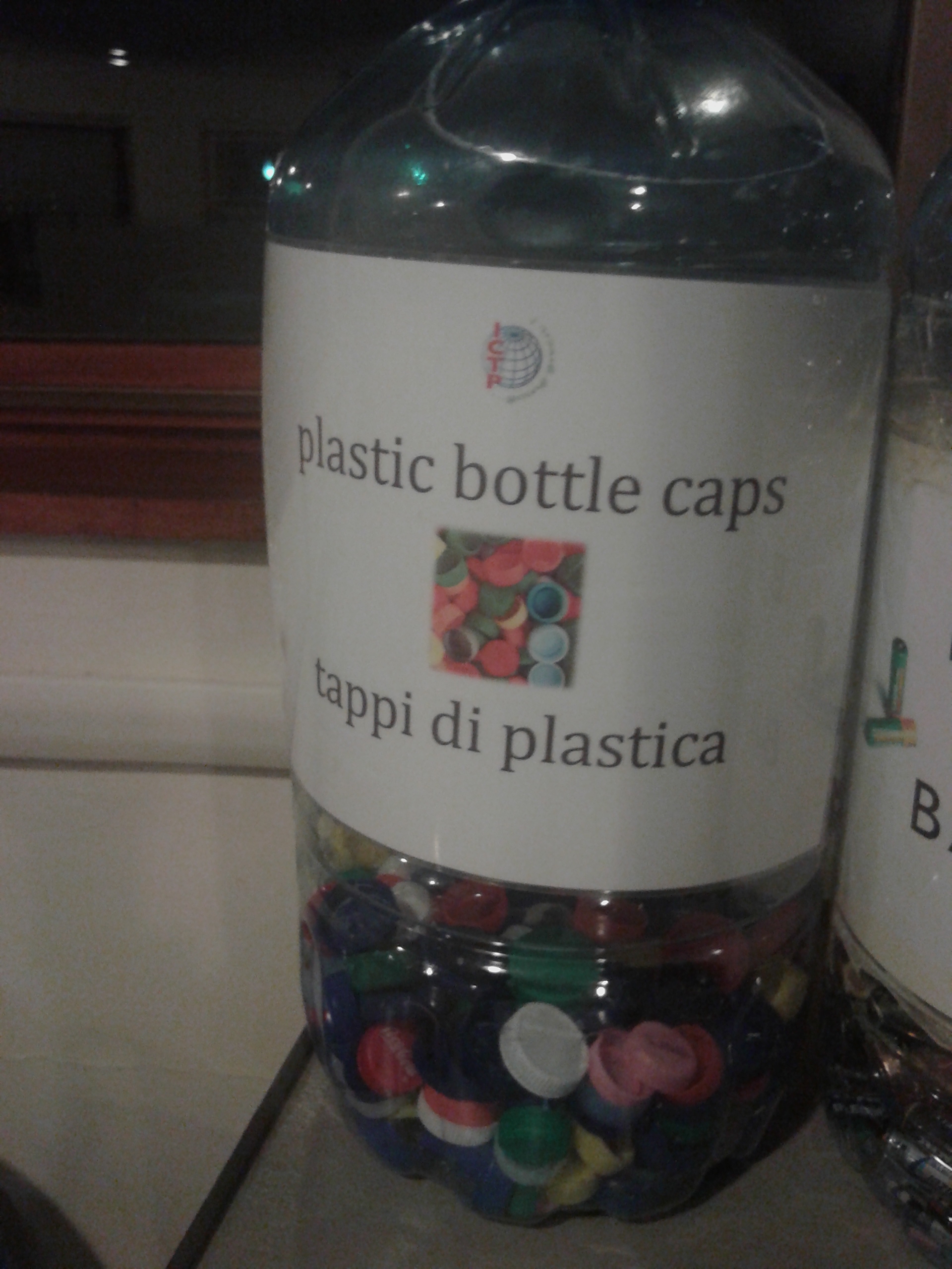
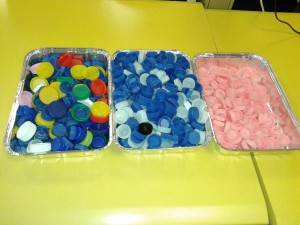
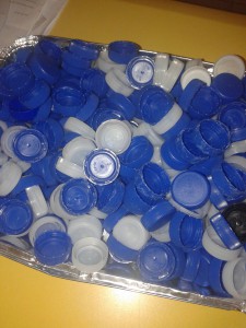
While Polypropylene (recycling code 5) is a very popular material to make bottle caps in many countries, in Italy, where we are located, most companies seem to prefer HDPE (recycling code 2) as a material for their plastic bottle-caps. We collected plastic caps in a nearby cafeteria and separated them by their material and color; this is where we noticed the Italian’s preference towards HDPE, since it made approximately 2/3 of the total of collected caps.

20141121_18414020141021_152430

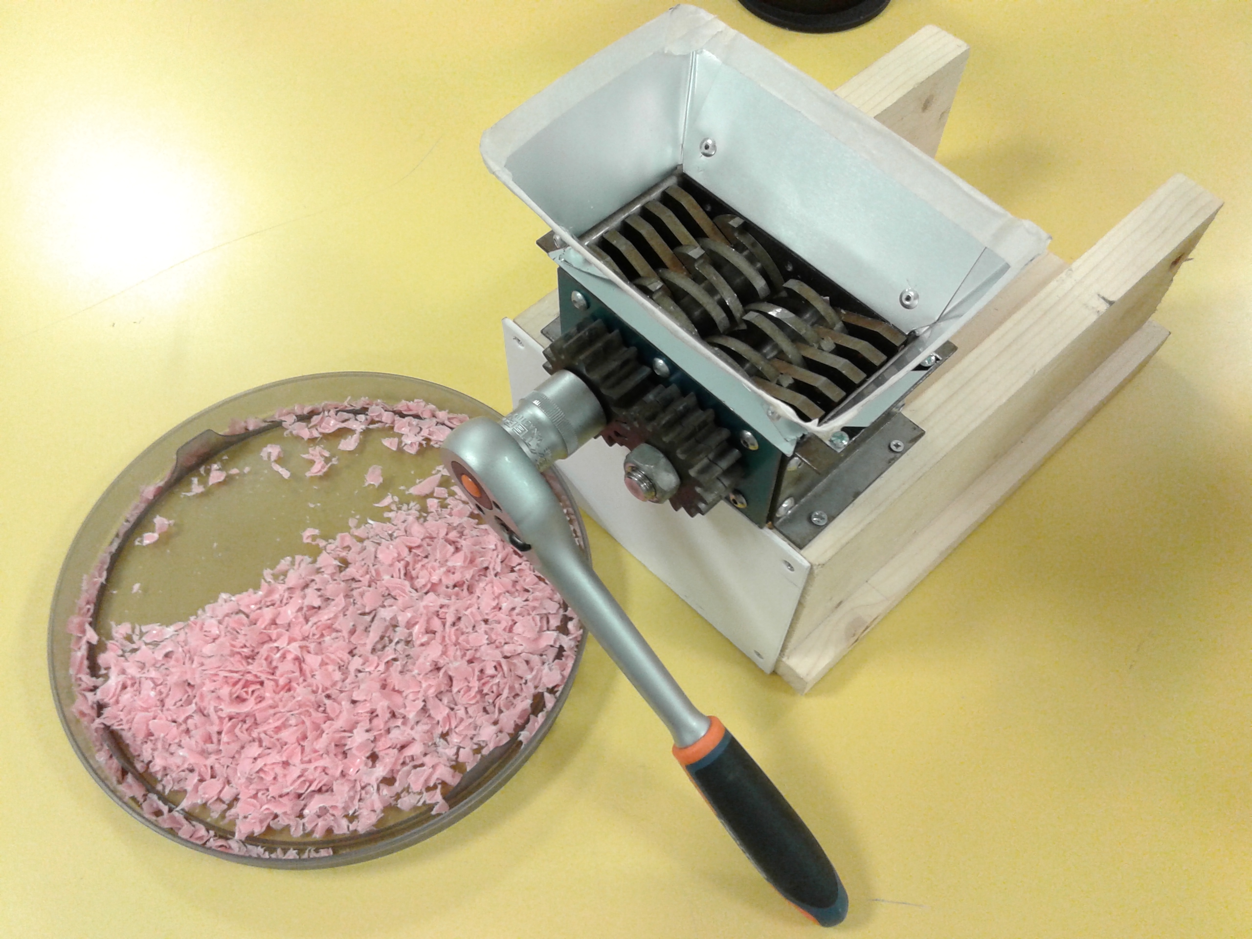
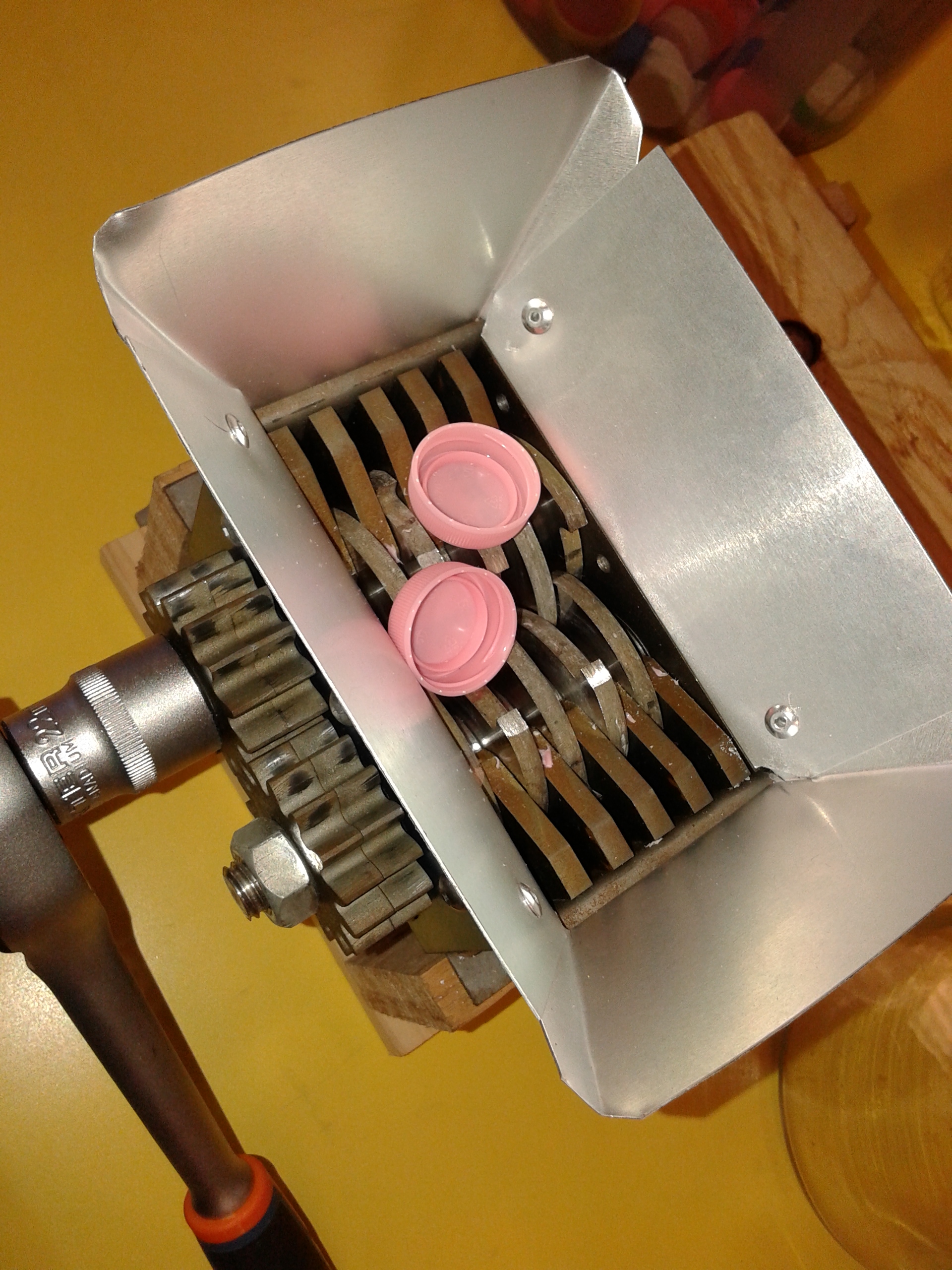
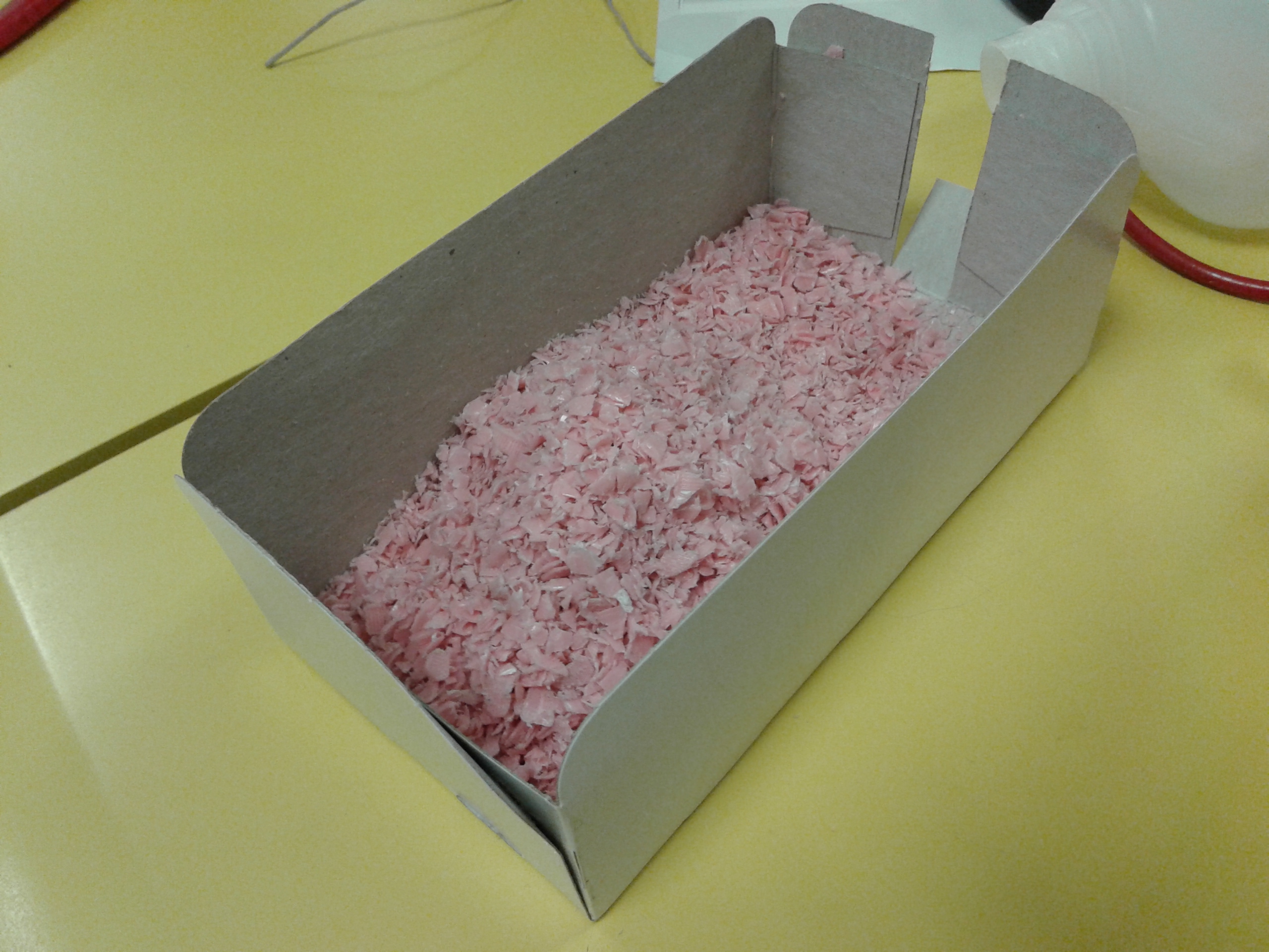
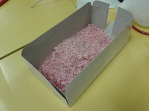
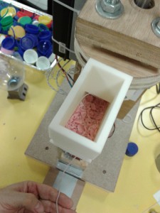
We started the process by shredding the pink-colored HDPE caps. This can be accomplished with some robust kitchen equipment or with specialized hardware.

20141112_174858 20141022_084212

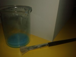
The resulting material needed to be dried before it goes into the filament extruder.

20141112_170120 20141112_170104

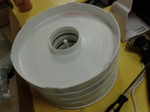
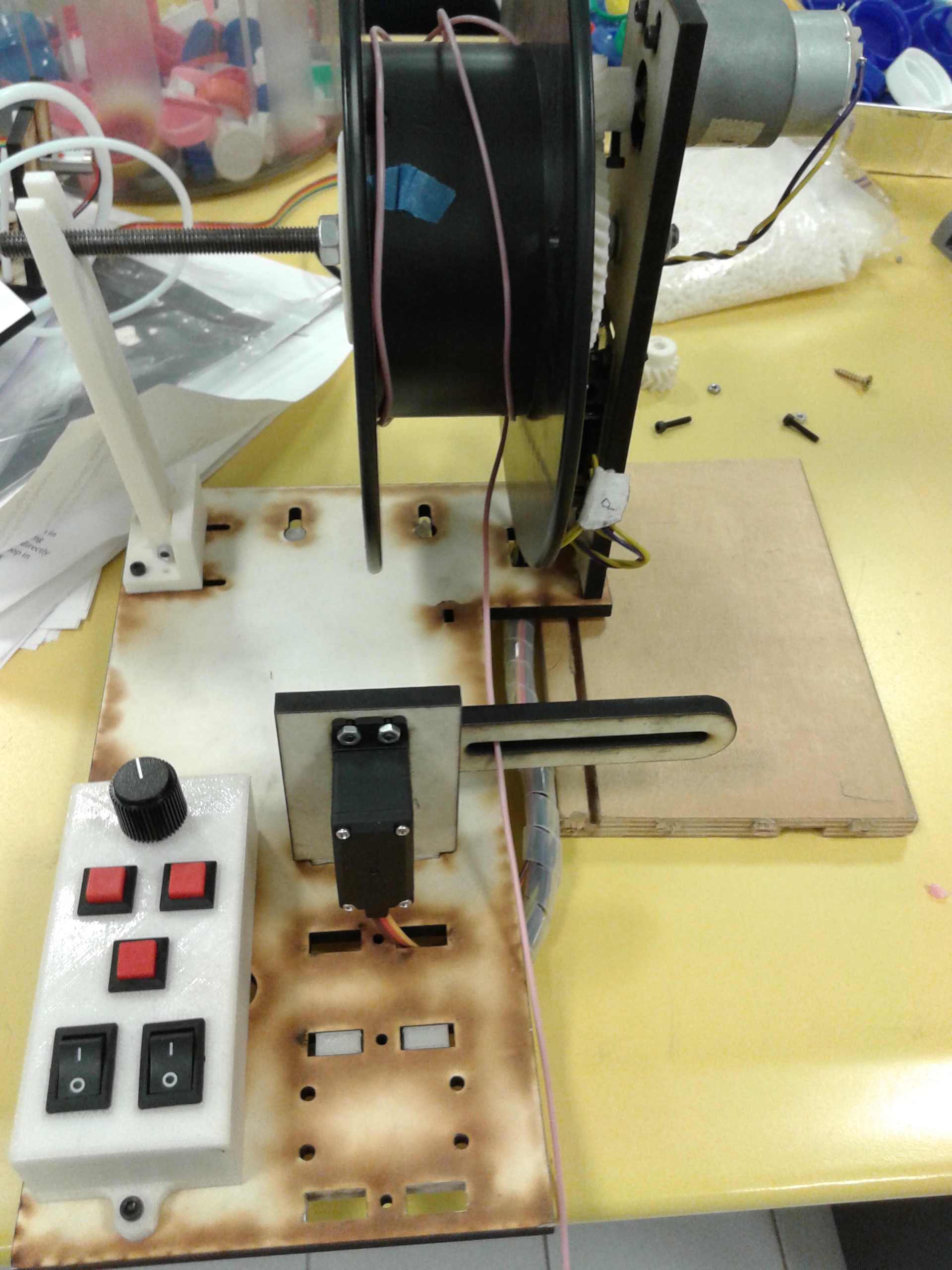
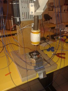
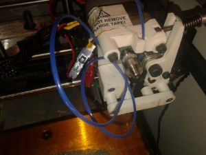
Then the filament extruder temperature was set to 132 C, and the feeding of the plastic could start. Each plastic cap will produce between 80 and 100 cm of filament at diameters around 1.75 mm.

20141112_170132 20141112_172005 20141112_171957 

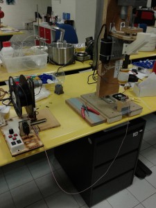
Keep in mind that the filament comes out of the extruder very hot and it is very irregular at first; you should make sure that the weight of the filament that is hanging, as well as the extruding temperature, feeding rate, pressure, etc., remain constant, so that the diameter of the filament reaches some uniformity. If you are doing this for the first time don’t feed the resulting filament into a Makerbot, or into some high-end 3D-printer, it will get clogged and your warranty won’t cover it, try to get some practice first and measure the diameter at several points, to make sure that it is constant and has the desired thickness.

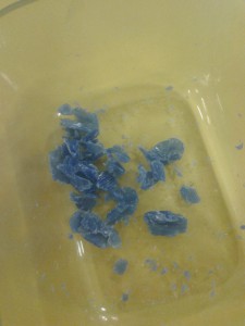
We repeated the same procedure with some blue HDPE caps and got a much nicer filament out of them, after all this was our second attempt :-)

20141121_180952 20141121_181027 20141121_180914

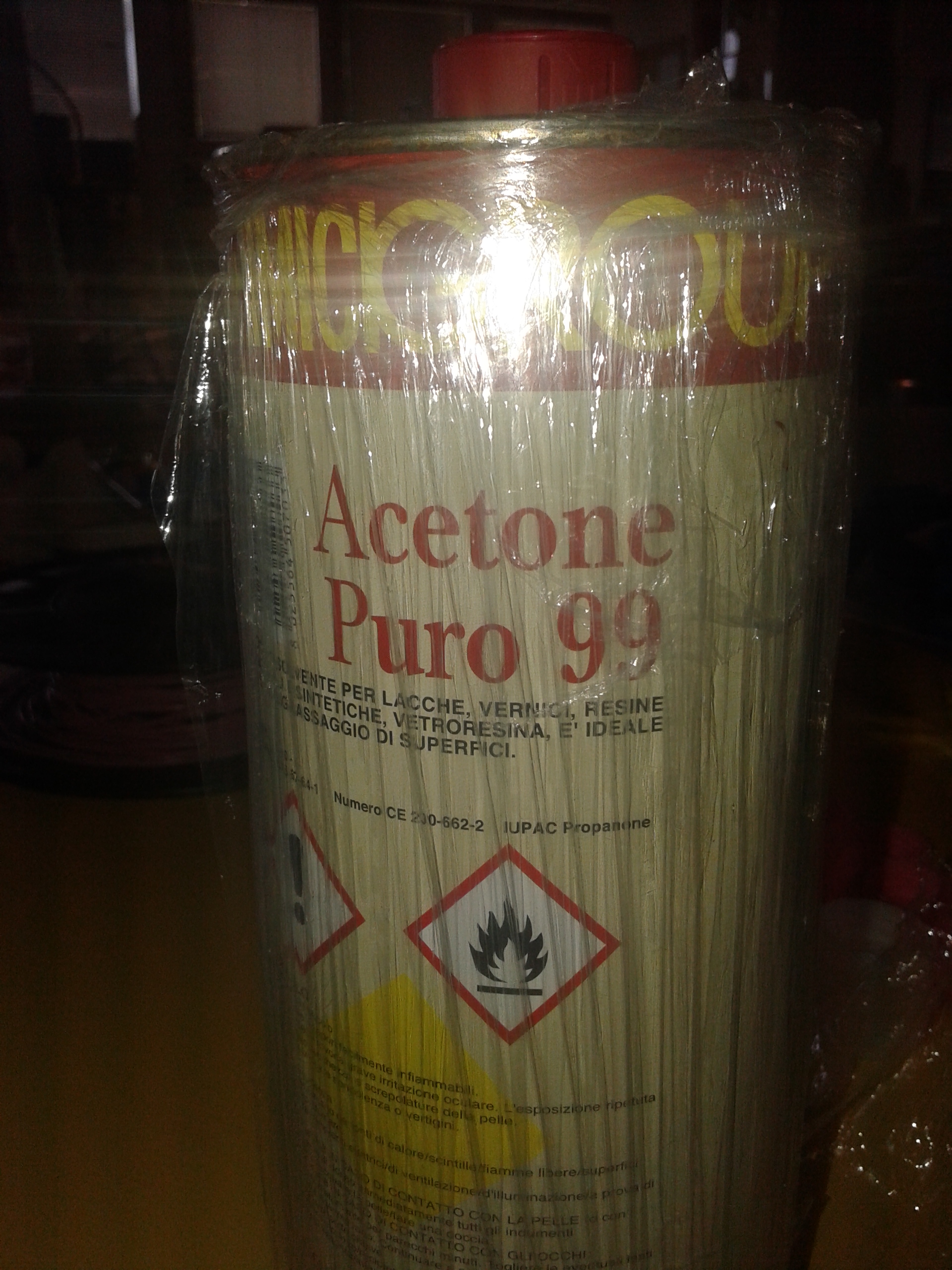
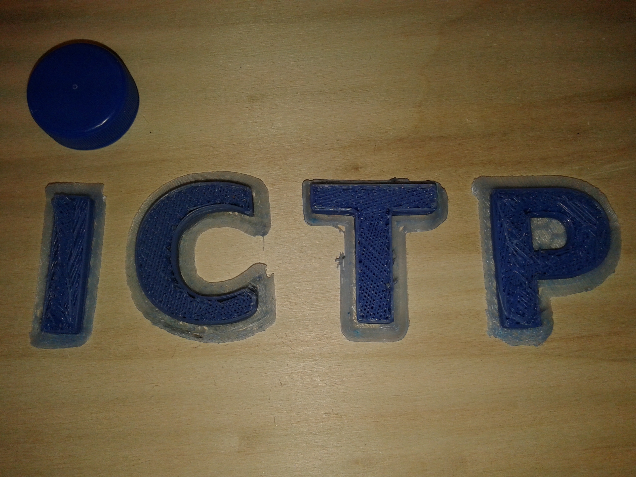
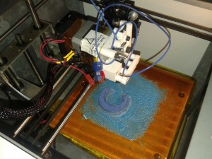
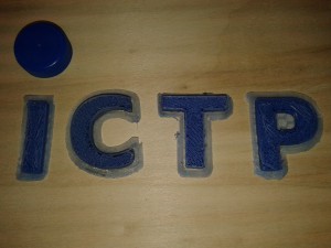
Now it comes the printing part. HDPE experienced a big contraction when it cooled after being extruded by the 3D-printer nozzle. We were not able to get it to stick for more than a few seconds to a clean and smooth hot surface, even after heating our printing bed up to 110 C, which exceeded the maximum bed-temperature in our Solidoodle 3D-printer. We then decided to prepare a mixture of ABS plastic with acetone and cover (paint) the plate with it.

20141122_113958 20141121_173455  20141122_113819

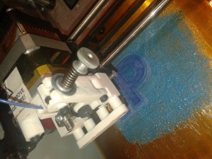
After this procedure the recycled plastic stuck nicely to the blue ABS layer, shown in the picture above.

The main challenge now was that the temperature that is required to guarantee a good flow of HDPE out of the printing nozzle seems to be 220 C or higher. The printer that we were using turned itself off at temperatures above 210 C, as a safety measure. The pink HDPE would stop flowing through the nozzle after just a few minutes because 210 C seemed to be very low for this type of plastic. The blue HDPE filament instead was a bit more amenable to flow at 210 C, but the stress that the extrusion gear was applying on it was too high and eventually surpassed its mechanical limit of stability, causing the filament to bend, which in turn caused it to stop going into the printer’s hot-end and nozzle.

20141121_17291620141122_120132

So far, the final result is not what you would expect from a high-quality filament, but there is still a lot of room for improvement in both extrusion processes, i.e., when producing filament and when printing with it. Have you also experimented with HDPE? Do you have experience with Polypropylene or other plastics not discussed in this post?  Let us know.

20141122_140259

Team:
• Carlo Fonda
Javier A. Montoya


We thank S. Faeta, M. Trivella, N. Bonaventure, and Tamara, for their collaboration during this project. For materials and equipment we received support from the ICTP’s Fabrication Laboratory, which is part of the Science Dissemination Unit (SDU) at ICTP.

Nov-2014

FishEyA – Live Broadcasting Around 360 Degrees

FishEyA – Live Broadcasting Around 360 Degrees

Presentation by SciFabLab at Virtual Reality Software Technologies (VRST) 2014:  We aim to build up a low-cost prototype system for cognitive studies around a live 360 degrees vision. Have, e.g., an original broadcasting channel that could transmit and cover in real time a panoramic vision at a distance and with minimal computation. Have developed an optimized software  to run in mini-computers like Raspberry and Banana Pi, BeagleBone having a light GUI to easily configure the 360° visual field and activate the streaming signal.

image_4

Lo SciFabLab citato sul sito di Make in Italy

L’ICTP ScifabLab e il recente esperimento di stampa 3D di una cinghia dentata per il restauro di una macchina “Programma 101” sono l’argomento dello splendido articolo di Alessandro Ranellucci apparso oggi sul sito web della Fondazione Make in Italy, l’importantissima realtà che rappresenta a livello nazionale il movimento dei maker e la rete dei FabLab italiani. Ringraziamo Alessandro per l’articolo e ne consigliamo a tutti la lettura!

Screen Shot 2014-11-12 at 18.45.23

In partenza per Lubiana!

Qualche settimana fa sono stata invitata a far parte di un bellissimo progetto che si svolge al MAO, il Museo per il Design e l’Architettura di Lubiana. Si può dormire nel museo a patto di presentare qualcosa, fare una mini conferenza o prendersi cura del museo e/o giardino. Volendo fare bella figura, ho deciso di presentare il mio progetto Cromopolis.

Dopo le famose battaglie perse con il software del laser cutter, mi sono arresa e ho preso alcuni dei vecchi file. Per la precisione gli unici che hanno sempre funzionato (gallina vecchia…). Il problema delle nuove forme generate con Adobe Illustrator ed esportate in formato .dxf per Inkscape, è rappresentato dal fatto che il software unisce dei punti apparentemente casuali (avrà una sua logica… spero). Quindi il risultato è che ad un punto, situato ad esempio al vertice di un arco di una finestra, ne viene collegato un altro non consecutivo ad esso, generando forme triangolari errate.

Cromopolis, taglio laser - Municipio

In conclusione: abbiamo girato di 20° le forme da incidere, in questo modo si genera un tratteggio inclinato che genera una texture molto più pronunciata rispetto al file perfettamente orizzontale. Con questo accorgimento abbiamo evitato di creare un file pesantissimo per ricreare una texture e alcune differenze di potenza del laser sono meno evidenti. Qui potete vedere il paragone tra le due prove.

Confronto stampe

Spesso la logica vera vince sulla tecnica. Eureka, avrebbe detto qualcuno.

Nuova cinghia 3D-printed per una Olivetti Programma 101

Un esemplare di Olivetti Programma 101 datato 1969 di proprietà dell’Università di Trieste è stato riparato da Giovanni de Sandre e Gastone Garziera in visita presso lo SciFabLab ICTP. Una cinghia dentata di difficile reperibilità, necessaria per far funzionare la stampante, è stata ottenuta tramite stampa 3D a basso costo, in Nylon, usando OpenSCAD, Slic3r ed una Printrbot Simple Metal. A riguardo potete anche leggere il bell’articolo che Alessandro Ranellucci ha scritto per la webzine della Fondazione Made In Italy.

Low-cost 3D printing of mathematical objects from IMAGINARY.ORG

The ICTP SciFabLab has hosted recently a project related to the challenge of making low-cost replicas of some mathematical surfaces that are part of the educational effort of IMAGINARY.ORG. Now the results are presented at a conference in Cape Town (South Africa), here you can find the presentations:

“Low-cost 3D Printing: Maths you can touch”

(duration: 60 min, 68 slides)

IMAGINARY_1 (PDF, 26 MB)

IMAGINARY_1 (PPTX, 345 MBWARNING: big file size!)

“Replicating the IMAGINARY collection of math objects using low-cost 3D printers”

(duration: 15 min, 18 slides)

IMAGINARY_2 (PDF, 5 MB)

IMAGINARY_2 (PPTX, 20 MB)

“Software tools and web resources to generate math objects for 3D-printing”

(duration: 30 min, 19 slides)

IMAGINARY_3 (PDF, 10 MB)

IMAGINARY_3 (PPTX, 25 MB)

Three related articles

extracted from the free open book on “Low-cost 3D Printing for Science, Education and Sustainable Development”, about OpenSCAD and K3DSurf (software tools to generate printable math objects)

  • 3D Modeling with OpenSCAD – Part 1
    by Sebastian Büttrich
  • 3D Modeling with OpenSCAD – Part 2
    by Marius Kintel
  • From Math to Jewel: an Example
    by Gaya Fior

excerpt_3DPrinting_Book (PDF, 11 MB)